Have you ever wondered what happens after pressing the “Cycle Start” button? When you press the green “CYCLE START” button on the operation panel, the machine tool starts moving according to the program. The whole process seems “magical” — but behind it is a very rigorous system collaborating: one component reads the program, another converts instructions into electrical signals, another drives the motor to rotate, another continuously detects position feedback, and another controls the coolant and tool change…
These “certain components” are the five core systems of CNC machine tools. Understanding these five systems is not just to satisfy curiosity — when the machine tool breaks down, you can roughly judge which link the problem is in; when you learn deeper knowledge, you will have a clear framework to understand new content.
System 1: CNC Device (CNC Controller) — The “Brain” of the Machine Tool
(Image source: Siemens) The CNC device is the core of the entire machine tool, which is what we often call the “CNC system” or CNC controller. Its working process is as follows:
Reading the program: Read the NC program from memory, CF card or network interface
Decoding: “Translate” instructions such as G-code and M-code into data that the system can process internally
Interpolation calculation: According to the motion instructions, calculate how much each axis needs to move in each time unit (this is the most core calculation — decomposing “from point A to point B” into countless tiny steps)
Issuing control instructions: Send the movement amount of each axis to the servo system in the form of electrical signals
Coordinating auxiliary functions: Control M-code functions such as spindle speed, tool change, and coolant
The CNC device not only passively executes the program, but also receives real-time position feedback from each axis and corrects motion deviations at any time. The operation panel and display screen you usually see on the machine tool are the human-computer interaction interface of the CNC device — you input programs, modify parameters, and check coordinates all through this interface to communicate with the CNC device.
System 2: Servo System — The “Muscles” of the Machine Tool
The CNC device issues an instruction of “X-axis moves 0.001mm”, but this instruction needs to be converted into real mechanical motion by the servo system. (Image source: FANUC)
The servo system consists of two parts:
Servo Drive: Receives the control signal sent by the CNC device, amplifies it, and converts it into electrical power to drive the motor. It is equivalent to a precision “power amplifier”.
Servo Motor: Converts electrical energy into mechanical rotational motion. The difference between a servo motor and an ordinary motor is that the servo motor has a built-in position encoder, which can precisely control the rotation angle, and its response speed is extremely fast — it can start, stop or change speed in milliseconds.
CNC machine tools usually have multiple sets of servo systems:
One feed servo for each of the X-axis, Y-axis, and Z-axis: Controls the movement of the tool and worktable
Spindle servo: Controls the rotation speed of the spindle (tool)
The focus of the spindle servo and feed servo is slightly different: the feed servo pursues position accuracy (the movement amount must be precise), and the spindle servo pursues speed stability (the speed must be constant during cutting, and cannot fluctuate due to changes in cutting force). For five-axis machine tools, there are two additional sets of servo systems to control the rotation axes (A/B/C axes), and there may be 5 to 6 sets of servos working at the same time.
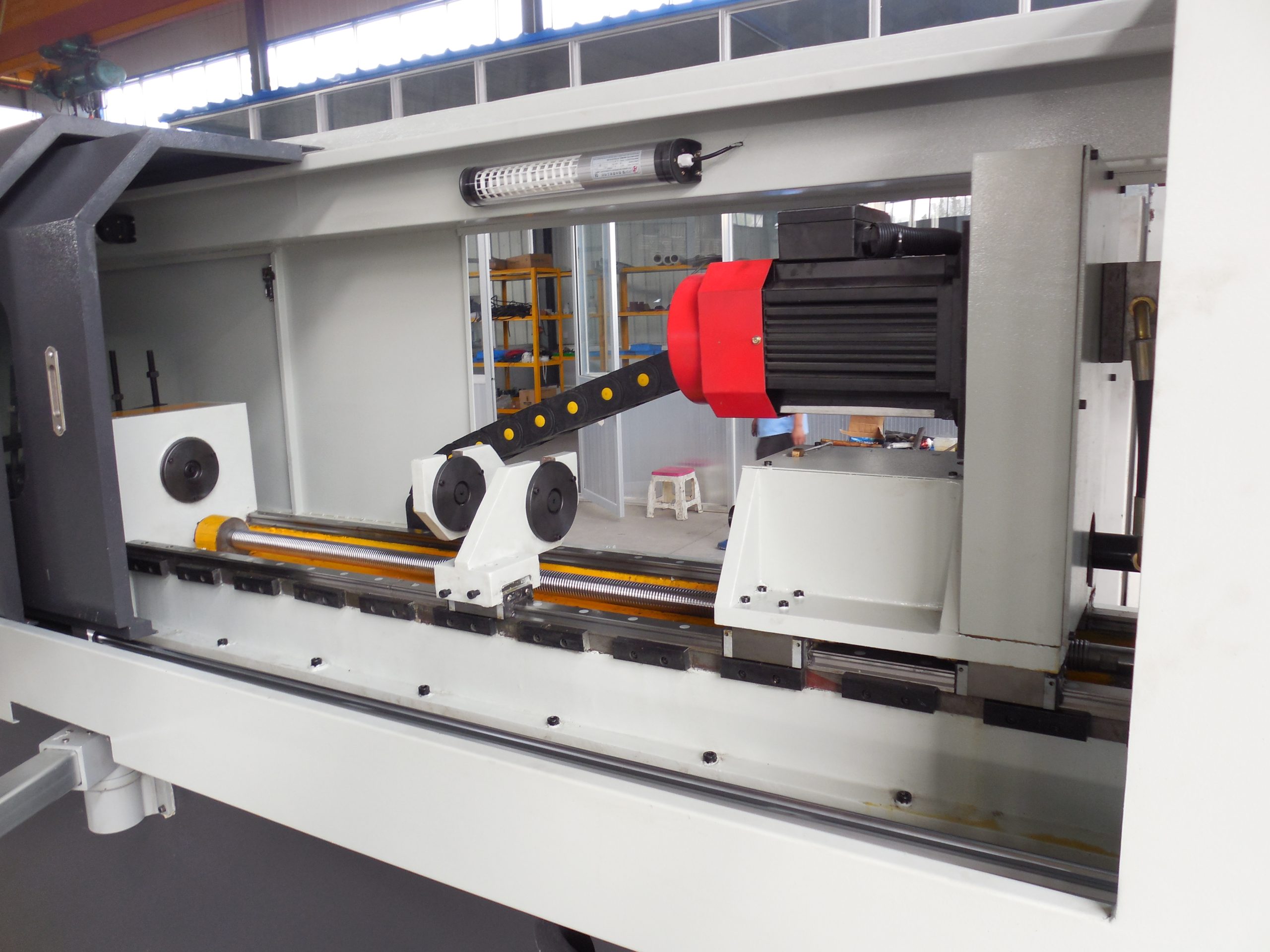
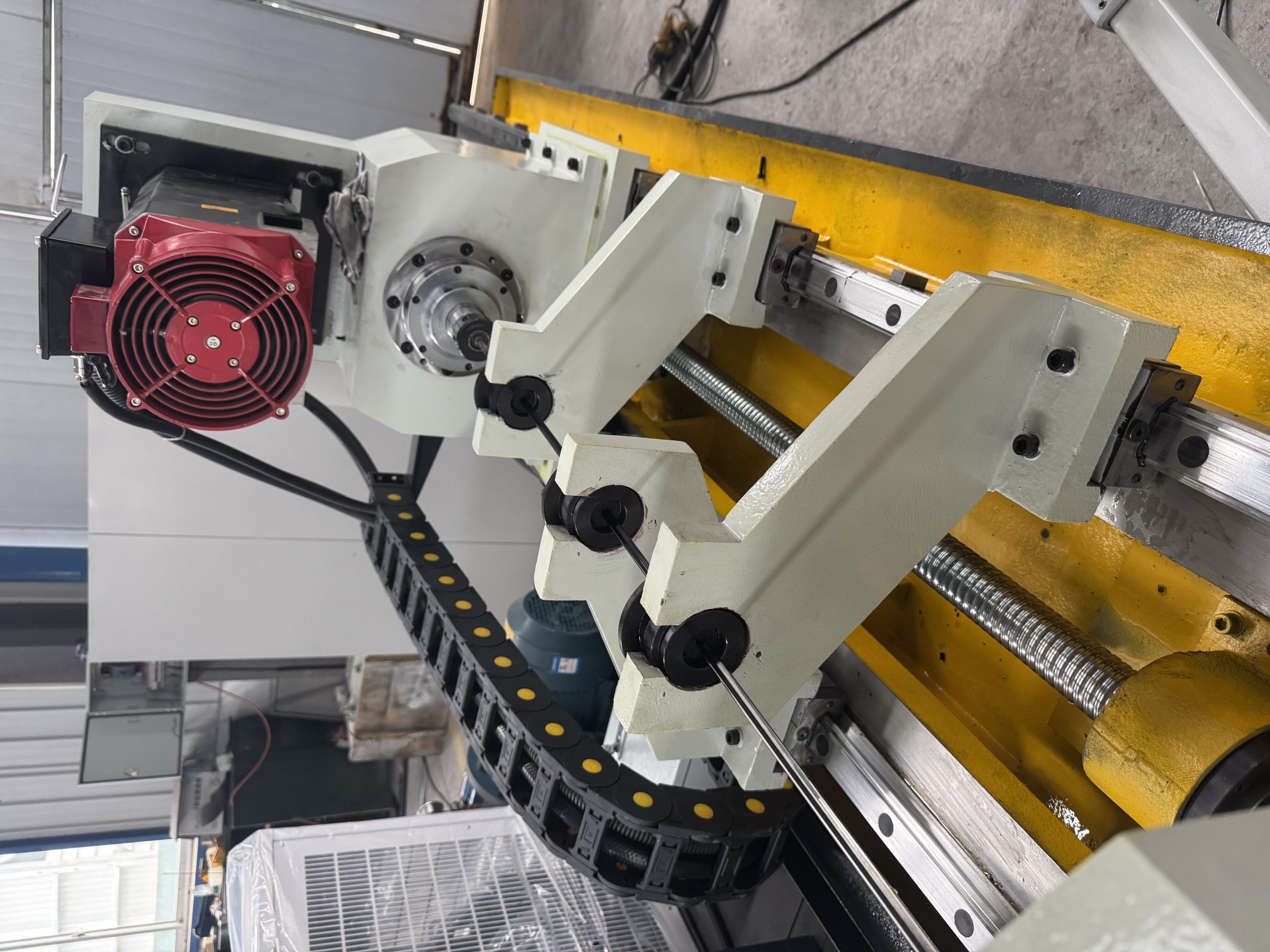
System 3: Machine Tool Mechanical Body — Skeleton and Joints
The servo motor generates rotational motion, but the machine tool performs linear movement and rotational positioning of the tool. It is necessary to convert the motor rotation into precise movement of various parts of the machine tool, which relies on the mechanical body. The core components of the mechanical body:
Bed / Frame: The basic structure of the machine tool, usually made of cast iron or welded steel plate. A good bed has high rigidity and good vibration resistance, which is the premise to ensure processing accuracy. (Two-line and one-hard three-axis optical machine)
Linear Guide / Way: The “track” that guides the worktable and spindle head to move in a specific direction. Modern machining centers generally adopt linear rolling guides, which have small friction, high precision and fast response. High-precision machine tools will use hydrostatic guides with almost zero friction.
Ball Screw: The core part that converts the rotational motion of the servo motor into the linear movement of the worktable. The ball screw transmits force through the rolling of internal steel balls, with extremely small friction, and can achieve micron-level positioning accuracy.
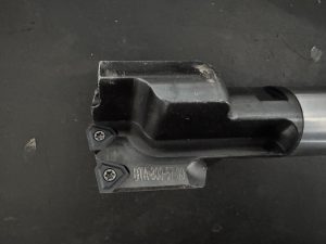
Spindle: The core component that clamps the tool and rotates at high speed. The accuracy (runout) of the spindle directly affects the processing accuracy, and the maximum speed of the spindle determines the speed at which you can process. High-speed spindles can reach 40,000 rpm or even higher. (Image source: Luoyi)
System 4: Detection and Feedback System — The Eyes of Closed-Loop Control
This is a very critical system that many beginners do not know much about. The CNC system tells the servo motor to “rotate 10 turns”, but how does it know that the motor has actually rotated exactly 10 turns? Has the tool actually moved the distance you requested? It relies on the detection and feedback system, whose function is to measure the actual position in real time and feed it back to the CNC device, allowing the system to automatically correct the deviation according to the error.
This cycle of “issuing instructions → executing → detecting actual values → comparing deviations → correcting instructions” is called closed-loop control, which is the core mechanism to ensure CNC accuracy.
There are two types of commonly used detection components:
Rotary Encoder: Installed on the servo motor shaft to detect the motor rotation angle. Since it detects the motor end rather than the worktable end, there are still errors such as screw elastic deformation, which belongs to semi-closed-loop control. Most machining centers adopt this scheme, and the positioning accuracy is usually ±0.005~0.01mm.
Linear Scale: Directly installed next to the machine tool guide rail to measure the actual linear displacement of the worktable. Because it directly measures the position of the worktable, it eliminates errors in transmission links such as the ball screw, belonging to full-closed-loop control with higher accuracy (up to ±0.001mm). High-precision machine tools and precision five-axis machine tools are generally equipped with linear scales. (RENISHAW linear scale)
System 5: Auxiliary Function System — Enabling the Machine Tool to “Work”
The first four systems together ensure that the tool can move precisely. But to truly complete the processing, a series of auxiliary functions are needed:
Automatic Tool Changer (ATC): One of the most important features of machining centers. The tool magazine stores multiple tools, and the manipulator automatically completes the entire process during tool change, usually only taking a few seconds. The capacity of the tool magazine ranges from 8 to more than 100 tools.
Cooling System: A lot of heat is generated between the tool and the workpiece during processing. The coolant is responsible for cooling, lubricating and chip removal. Common methods include external spray cooling, internal cooling (spraying directly to the cutting area through the spindle and tool center hole), etc.
Pneumatic/Hydraulic System: Used for actions that require large force such as clamping workpieces, tool change actions, and spindle tool release.
PLC (Programmable Logic Controller): The CNC device only manages motion control, while a large number of switch quantity controls on the machine tool (tool change, coolant switch, protective door interlock, etc.) are handled by the built-in PLC. The PLC and the CNC device cooperate to form a complete machine tool control system.
Signal Flow of the Five Core Systems (Understand at a Glance)
The working process of the entire system can be understood with a signal chain: this is everything that happens after “pressing the cycle start”, a precise closed-loop control process that repeats thousands of times per second.
Introduction to Mainstream CNC System Brands
After understanding the role of the CNC device, let’s get to know the main brands on the market:
FANUC: A Japanese brand with the largest global market share and extremely high occupancy rate in domestic factories. The system is stable and reliable, with a complete technical ecosystem, making it the first choice for entry-level learning (the subsequent operation examples in this series will mainly focus on FANUC).
Siemens SINUMERIK: A German brand, the mainstream configuration of European-style machine tools. SINUMERIK ONE is a high-end machine tool installation system with powerful functions and perfect five-axis support, but the learning curve is steep. It is widely used in domestic automotive and aerospace fields.
Heidenhain TNC: A German brand focusing on milling machining centers, with the most refined five-axis function support, and a high reputation in the aerospace and precision mold fields.
Domestic brands have developed rapidly in recent years, and the main representatives are as follows:
| Marka | Affiliated Company | Esasy artykmaçlyklary | Market Positioning | Five-Axis Support |
| Huazhong Type 9 | Huazhong CNC | Domestic CPU, independent and controllable | Mid-to-low end, domestic replacement | General |
| GSK | Guangzhou CNC | Price advantage, complete supporting facilities | Economical machine tools | General |
| Kede GNC62 | Kede CNC | Five-axis linkage and turn-mill composite processing | Mid-to-high end market | Gowy |
| Syntec | Syntec Technology | Strong CAM compatibility, user-friendly interface | Mid-end, fastest growing in the five-axis field | Gowy |
Special Focus: Syntec System — The Main Force of Domestic Five-Axis
Among many domestic CNC systems, Syntec has performed particularly prominently in the five-axis processing field in recent years and has become one of the systems with the highest installation rate of domestic five-axis machine tools.
The core advantages of Syntec are: extremely strong CAM software compatibility, supporting the post-processing output of almost all mainstream CAM software; G-code is basically compatible with FANUC CNC systems, the operation interface is user-friendly for beginners, and the learning cost is lower than that of traditional European and American systems; at the same time, it performs stably in key functions such as five-axis RTCP and tool axis control, which is an important reason why a large number of five-axis machine tool manufacturers choose Syntec as the standard configuration system.
If you or your company is planning to purchase a domestic five-axis machine tool, or want to understand the development status of domestic systems, you can pay attention to the Syntec system, which also has abundant learning resources online. In the subsequent practical operation demonstrations of this series, we will also consider adding operation examples of the Syntec system.
Summary of This Article
· CNC Device: The brain, which reads programs, performs interpolation calculations, and issues motion instructions
· Servo System: The muscles, which drive the precise movement of each axis motor
· Mechanical Body: The skeleton, including bed, guide rail, ball screw, and spindle
#CNCMachineTools #CNCCoreSystems #FANUCSiemens #FiveAxisMachining #SyntecSystem #CNCTechnology #CNCMachining