

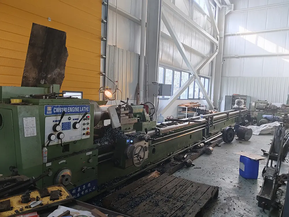
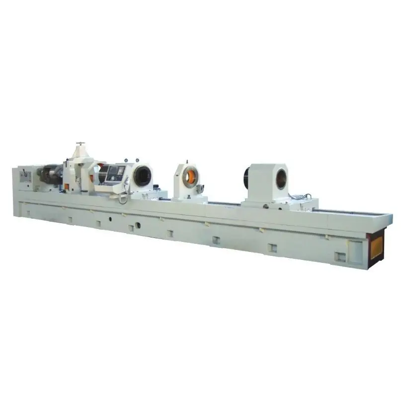
Large aperture deep hole drill i a deep hole machining machine that integrates BTA drill cutter drill,and gun dril,with a driling diameter of up to φ120mm.
High efficient,high-precision,and high smoothness machining of large holes,with a smoothness of Ra0.4~0.8.

Horizontal layout; simultaneously supports both gun drilling (external chip removal) and BTA (internal chip removal) machining modes. These two modes cannot be used concurrently; for example, BTA cannot be used while gun drilling is in operation. The workpiece is fixed to a dedicated fixture, and the tool rotates and feeds.
BTA can only machine coaxial holes, while gun drilling can machine both coaxial and eccentric holes.
Employs a dual-spindle structure; the gun drill rod box and the BTA drill rod box are mounted on a single support plate, sharing a common feed system.
CNC System: KND system
Servo Axis: Z-axis, controls tool feed
Machining Diameter Range:
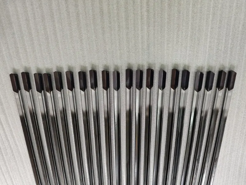
Gun Drill: Φ5mm~Φ30mm
BTA: Φ25mm~Φ80mm
Maximum Machining Depth: 1000mm

Drilling Deviation: 1mm/1000mm
Roughness: Ra0.8~Ra6.3um
Dimensional Accuracy: IT8~IT11
Workpiece clamping during BTA machining: The workpiece is clamped and positioned using chamfered ends, a tapered disc, a guide sleeve, and a hydraulic system. The workpiece is first placed on an auxiliary support, and the hydraulic system controls the tapered disc to press against the chamfered ends of the workpiece, achieving workpiece clamping and positioning.
Workpiece clamping during gun drilling: The workpiece is placed on a V-block and manually clamped. The gun drilling fixture can move laterally, suitable for eccentric hole machining, with a travel stroke of 150mm. Replace the pads on the V-block when the workpiece diameter is different.
(1) Simultaneously supports both gun drilling (external chip removal) and BTA (internal chip removal) machining methods.
(2) The bed, housing, worktable, and other basic components are made of high-quality cast iron.
(3) A suspended CNC system operating table facilitates machine tool operation. (4) Equipped with a dedicated cooling system: consisting of an automatic chip conveyor, oil cooler, filtration system, and high-pressure pump unit.
(5) Employs the KND system.
(6) The Z-axis feed guide is a double rectangular sliding guide, providing high rigidity.
(7) Tool rotation is driven by the spindle motor, and tool feed is achieved through a servo motor driving a ball screw. Both tool rotation and feed are infinitely variable.
(8) The main unit uses a flow-type protective cover.
(9) Electrical system: Employs the KND CNC system, which can be programmed to complete automatic machining cycles, and also allows for manual, jogging, and on/off adjustments.
(10) The machine tool has functions such as pressure protection, cooling system liquid level and temperature protection, tool protection, and stroke protection.
| Technical Specifications | parameter | Remark | ||
| Scope of work | Drilling diameter range | Gun drill: Φ5~Φ35mm | ||
| BTA:Φ25~Φ80mm | ||||
| Maximum drilling depth | 1000mm | |||
| Maximum workpiece length | 1000mm | |||
| Machine tool performance | Gun drill rod box | Speed range | 600~6000rpm | Variable |
| Main motor power | 5.5KW | spindle motor | ||
| BTA Drill Pipe Box | Speed range | 200~2000rpm | Variable | |
| Main motor power | 30KW | spindle motor | ||
| Z-axis | Feed rate range | 5~500mm/min | Variable | |
| Fast movement speed | 2000mm/min | |||
| Motor torque | 20Nm | |||
| other | Drill length-to-diameter ratio | ≤100 | ||
| Total power of the machine tool (approximately) | 85kW | |||
| Machine tool floor space (approximately) | 7m (length) × 3m (width) | |||
| Machine tool weight (approx.) | 12 tons | |||
| CNC system | FANUC 0i Mate TD system | |||
| Cooling system | Cooling system pressure range | 1~10MPa | Adjustable | |
| Cooling system flow range | 100、200、300L/min | Adjustable | ||
| Filtration accuracy | 40μm | |||
1. Machine Bed
Made of high-quality cast iron with a closed casting structure, providing the machine tool with sufficient rigidity and strength. Double rectangular sliding guideways are machined onto the bed, and these guideways undergo medium-frequency quenching.
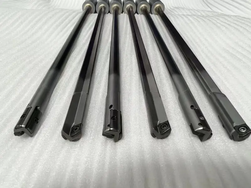
2. Drill Rod Box
Main components: Drill rod box for gun drills, drill rod box for BTA (Boiler Actuation), and feed slide.
Two drill rod boxes are mounted on the slide.
Drill rod box for gun drills: Drives the tool rotation and supplies oil to the tool.
Drill rod box for BTA: Drives the tool rotation and provides a chip removal channel for drilling.
Common features of both drill rod boxes: Spindle motor drives spindle rotation with stepless speed regulation; rear-mounted main motor prevents cutting oil from entering the motor and facilitates tool changing; high-precision angular contact ball bearings with automatic lubrication.
3. Feed System
Uses an AC servo system for drive, with stepless speed regulation, ranging from 5 to 500 mm/min. Utilizes a ball screw drive. The feed guide is a double rectangular sliding guide, which is hardened by medium frequency and precision ground, thus possessing advantages such as high precision, long service life, high rigidity, and good accuracy retention.
4. Cooling System
Equipped with a dedicated cooling system, providing high-pressure, high-flow-rate, and high-cleanliness cutting fluid for deep hole drilling.
Automatic chip conveyor: Automatically removes chips, achieving initial oil-chip separation.
Oil cooler: Controls cutting fluid temperature and prevents cutting fluid deterioration.
Filtration system: Paper tape, mesh, and magnetic rod filters improve cutting fluid cleanliness.
High-pressure pump set: Generates cutting oil with adjustable flow and pressure to supply oil to the cutting tools.
5. Centralized Lubrication System
The front and rear bearings of the drill rod box spindle, the slide guide surfaces, etc., are all automatically lubricated with timed and metered lubrication. The oil tank has an automatic low oil level alarm function.
6. Electrical System
Employs a KND system, which can be programmed to complete automatic machining cycles, and can also be manually operated, jogged, and adjusted for start/stop. The CNC system control panel is suspended.
It features ladder diagram display, is programmable, and supports Chinese display.
It has reliable interlocking, safety protection, over-torque protection, or other fault diagnosis, alarm, and protection functions, emitting audible and visual signals (red, yellow, and green column lights).
7. Guide Frame and Oil Feeder
The guide frame and oil feeder are mounted on the slide. The slide is axially moved by the guide sleeve controlled by the hydraulic system to tighten or loosen the workpiece.
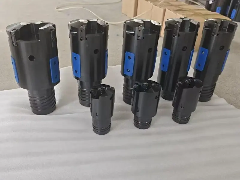
Guide Frame: Used for gun drilling; Functions: drill bit guidance, oil sealing, chip removal, and tool holder support.
Oil Feeder: Used for BTA (Boiler Actuation) machining; Functions: drill bit guidance, oil sealing, tool oil supply, and tool holder support.
8. Drill Rod Support
Two sets, providing drill rod support and vibration damping.
9. Hydraulic System
Controls the guide frame and oil feeder to tighten or loosen the workpiece, and provides a seal during drilling to prevent cutting fluid splashing.
10. Fixtures
BTA: Utilizing chamfered ends, a tapered disc, guide sleeves, and a hydraulic system, the workpiece is clamped and positioned. The workpiece is first placed on an auxiliary support, and the hydraulic system controls the tapered disc to press against the chamfered ends of the workpiece, achieving clamping and positioning.
Gun Drill: The workpiece is placed on a V-block, and a hydraulic rotary cylinder automatically clamps the workpiece. The gun drill fixture can move laterally, suitable for machining eccentric holes, with a travel stroke of 100mm. When the workpiece diameter is different, the pads on the V-block can be replaced.
11. Sliding Semi-Protective System
The machine bed is equipped with oil baffles and a sliding door, fully considering the convenience of loading and unloading workpieces and tools.
Accessories: Special order, cost borne by the user.
Cutting Tools: Provided by the user or procured by us, used for pre-acceptance and final acceptance of the machine tool, cost borne by the user.
Cutting Oil: Provided by the user for final acceptance.
One copy of the machine tool instruction manual, one copy of the certificate of conformity, and one copy of the packing list. One copy of the CNC system operation and maintenance manual.
1. Pre-acceptance by the user at the machine tool manufacturer's factory. Machining one workpiece; test piece and cutting tools provided by the user; acceptance according to item 2.
2. Final acceptance at the user's factory. Machining two workpieces; test piece and cutting tools provided by the user; acceptance according to item 2. Upon successful completion, both parties sign the final acceptance minutes, which become effective upon signature.
1. Installation and Commissioning
After the machine tool arrives at the user's factory, the machine tool manufacturer will send personnel to guide the equipment installation and be responsible for commissioning.
2. Training: The machine tool manufacturer will provide three working days of training for the user's programming, operation, and maintenance personnel. During the training, the manufacturer will guide the user's technical and operational personnel to conduct trial production on typical parts.
3. The machine tool manufacturer strictly adheres to the after-sales service commitments of Dezhou Delong (Group) Machine Tool Co., Ltd.
4. The equipment is covered by a one-year warranty.
Product parameter Model Basic Configuration NEXUS-4000-Ⅲ Control System: MATRIX ...
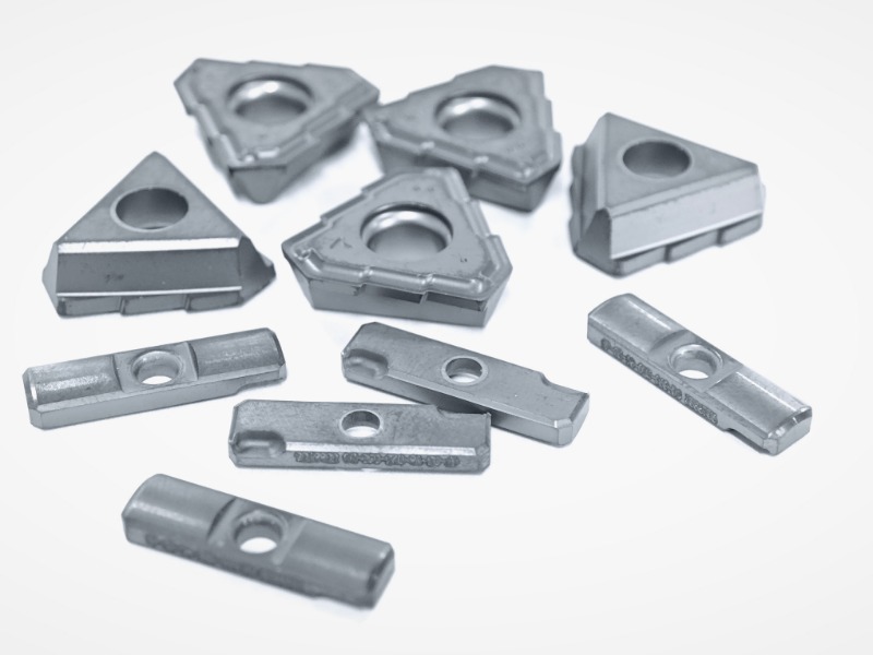
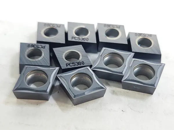
Square CNC turning inserts are one of the commonly used cutting tools in CNC turning processes.
A Composite Sheet Substrate refers to a base material, typically in sheet form, that is composed of two or more distinct physical or chemical phases combined to create a new material with superior properties compared to its individual components. In advanced industrial contexts, this often involves combining a tough, ductile matrix (like a metal or polymer) with a hard, reinforcing phase (like ceramic particles or fibers) to achieve a balance of strength, toughness, and other specific functional properties. These substrates are engineered to serve as a foundational platform for further processing or as a core structural component in demanding applications.
Comma face grooving cutters (also known as comma grooving cutters or face comma cutters) are spec...
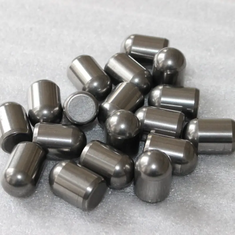
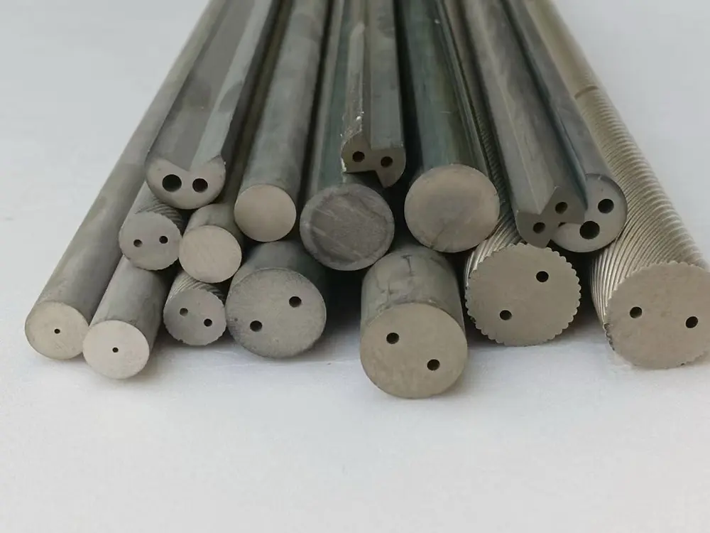
Carbide cutting teeth refer to the tooth-like or tip components made from tungsten carbide, a composite material known for its exceptional hardness, wear resistance, and durability. These teeth are typically brazed or mounted onto various tools and machinery to serve as the primary cutting, drilling, or grinding surface.
DIAMETERS FROM .0393” (1.0 MM) TO .4375” (11.1 MM) LENGTHS OF CUT FROM 5” (127 MM) – 14.17” (360MM)
Our triple-blade end mills combine precision manufacturing (5-axis grinding) and premium materials (e.g., YG10X carbide) to deliver consistent performance in industrial production.
This machine tool is a special-purpose machine tool for machining cylindrical deep-hole parts. It is suitable for boring cylindrical deep-hole workpieces. During boring, an oil feeder is used to supply oil, and the chips are discharged to the chip hopper at the head of the machine through the cutting zone. During drilling, an internal chip removal method (BTA) is used, that is, an oil feeder supplies oil, and the chips are discharged from the inside of the drill rod to the chip hopper at the rear of the machine through the cutting zone.

Nickel-based corrosion-resistant alloys are a class of advanced metallic materials engineered primarily to withstand extreme corrosive environments. Their foundation is a nickel (Ni) matrix, which is inherently resistant to many corrosives, alloyed with other key elements—primarily chromium (Cr), molybdenum (Mo), and sometimes copper (Cu) and nitrogen (N)—to create a versatile and powerful family of materials for the most aggressive chemical and industrial applications. They are the go-to solution when stainless steels are no longer sufficient.
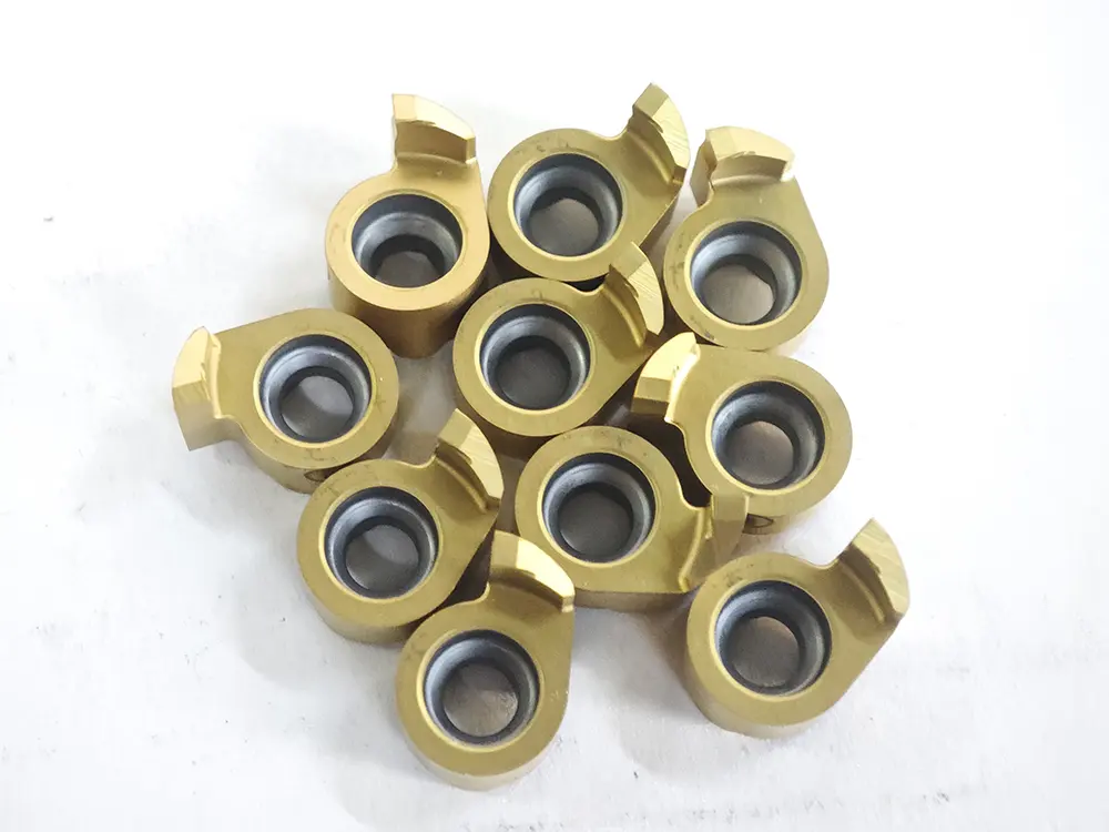
Core Definition and Structure Grooving inserts are preformed replaceable cutting unit...
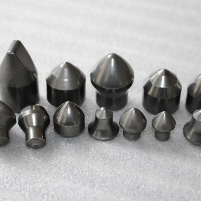
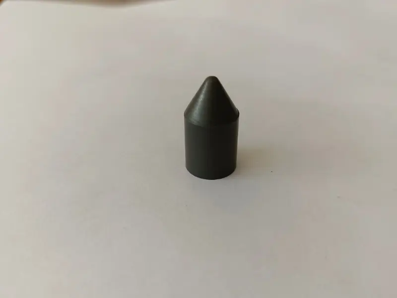
Cemented carbide tapered ball tooth is a key cutting component of geological and mining equipment (such as DTH drills, roller cone drills). It adopts a tapered structure design, and the ball head has excellent impact toughness and wear resistance. It can effectively crush hard rocks and ores, and is suitable for drilling, blasting and other operations. It has the advantages of high crushing efficiency, strong impact resistance and being not easy to damage.
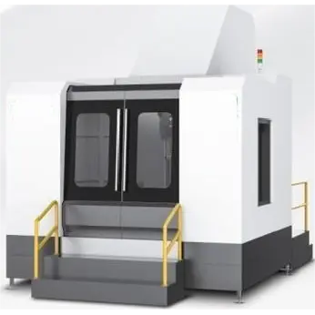
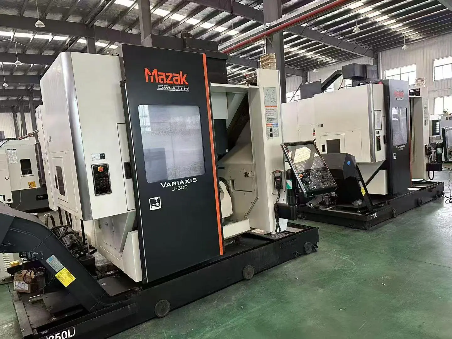
The RFD6ZX1010-1000 six-axis drilling and milling compound deep hole drilling machine is mainly used for deep hole drilling and milling. Equipped with a high-precision CNC turntable (B-axis) and a sliding table rotation axis (A-axis), it can complete five-sided drilling and milling with one clamping. This expands the machine’s processing range, reduces clamping times, greatly improves processing accuracy and efficiency, and effectively saves production costs. It is mainly used for oblique hole processing in molds, mechanical parts, etc.
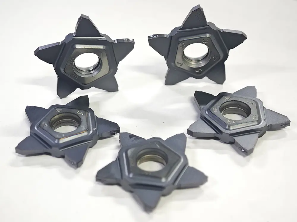
Star-shaped Grooving Cutters (also referred to as Penta Grooving Tools) are cost-effective indexable tools for CNC grooving and parting operations. They are named for their pentagram-shaped insert structure with 5 cutting edges, and are primarily suitable for machining shallow grooves, wide grooves, parting cuts, and shoulder grooves—especially ideal for small part and batch production scenarios.
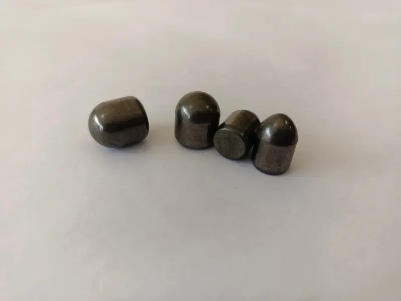
Cemented carbide ball tooth is a multi-functional cemented carbide cutting/crushing component with a spherical head. It has excellent impact toughness, wear resistance and cutting performance. Widely used in mining, tunnel excavation, building crushing and other fields, it is installed on drilling rigs, crushers, excavators and other equipment. It can efficiently crush hard materials such as rocks, ores and concrete, and is a key wearing part in the geology, mining and construction industries.
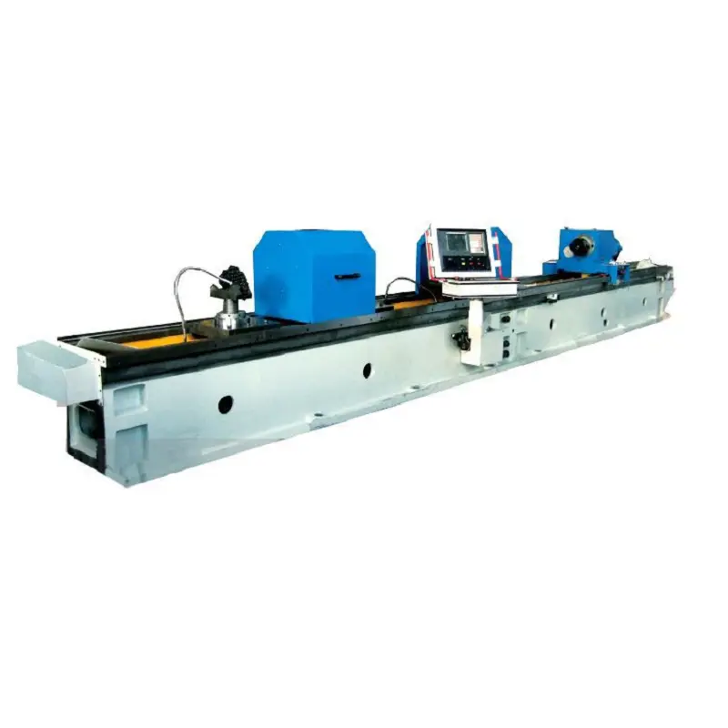
The usage of 2M2125A 2M2135A Deep Hole Honing Machine is a special equipment used for honing cylindrical deep hole parts such as various hydraulic oil cylinders and cylinders. Hole Diameter accuracy of machined workpieces can be up to or over IT7 and surface roughness Ra0.2-0.4μm. It can also repair and maintain taper and ellipticity of machined workpieces with the help of partial honing.